Intrinsic safety explosion protection limits the spark and thermal energy in a hazardous area to below the level which can cause ignition of a gas or the combustion of a dust. By definition it is a low power technique which provides the highest level of electrical equipment protection in a flammable atmosphere. Apart from a few special exceptions, it is the only protection technique that may be used in Zone 0 or 20 where a hazard is continuously present for long periods, and the only technique which allows live maintenance to be performed.
Intrinsic safety explosion protection limits the spark and thermal energy in a hazardous area to below the level which can cause ignition of a gas or the combustion of a dust. By definition it is a low power technique which provides the highest level of electrical equipment protection in a flammable atmosphere. Apart from a few special exceptions, it is the only protection technique that may be used in Zone 0 or 20 where a hazard is continuously present for long periods, and the only technique which allows live maintenance to be performed.
The concept of intrinsic safety was first introduced in the early twentieth century to prevent signalling systems in coal mines igniting firedamp which is predominantly methane, plus more volatile gases. By the late 1940s national intrinsic safety standards were being published, BS1259 appeared in November 1945 and a few instruments with intrinsically safe inputs such as chart recorders became available. In the 1960s the first shunt diode Zener barriers, which limit the transfer of energy from a safe to a hazardous area, were starting to be introduced by a number of instrument suppliers. These allowed any general purpose safe area equipment to be connected to hazardous area sensors without the need for third party approval of the safe area apparatus. This modular approach greatly simplified intrinsic safety system design, but introduced cable parameters and Simple Apparatus.
By the mid 1980s the shunt diode Zener barrier was joined by the galvanic isolator, which satisfied the initial German preference for all intrinsically safe circuits to be isolated. The galvanic isolator performs the same function as the Zener barrier, but has a floating output and does not require a high integrity earth connection. International IEC / ATEX standards arrived in the early 2000s and continue to evolve, the latest edition of IEC 60079-11 Equipment protection by intrinsic safety being published in 2023.
Initially intrinsic safety was mainly used for transferring the output of hazardous area sensors such as thermocouple, RTDs, strain gauges and switch contacts from a hazardous to a safe area. The availability in the mid to late 1960s of semiconductors which function at low voltages and currents, enabled active intrinsically safe hazardous area equipment powered from the safe area via a Zener barrier or galvanic isolator to be developed. Proximity detectors and loop powered transmitters of ever improving performance were gradually introduced. The advent of integrated circuits and more recently low power microcontrollers further increased applications.
Despite clever techniques to increase intrinsically safe power, such as Power-i which utilise electronically controlled spark duration limitation, after more than a century of development, practical intrinsic safety remains a low power technique. Commercially available Zener barriers and galvanic isolators can supply about 0.8W of matched power to a load in a hydrogen atmosphere. Whilst this is perfectly acceptable for a vast range of instrumentation applications, it limits hazardous area apparatus powered from a safe area to very low power electronics, but with innovative design it is possible to increase the usable power in a hazardous area by a factor of about five.
There are three separate but related areas that need to be considered to increase usable power:
International intrinsic safety standards include ignition curves for resistive limited sources which define the minimum voltage and current that may cause the ignition of three different gas groups IIA propane, IIB ethylene and IIC hydrogen. For connection to hazardous area apparatus located in Zone 0 where a hazard is continuously present for long periods (>1000hours/year), or to apparatus in Zone 1 where the hazard is less likely to occur in normal operation (>10 <1000hours/year), international standards specify that a 1.5 factor of safety must be applied to these ignition curves. The resulting figures define the absolute maximum permitted output voltage Uo and output current Io of the interface between the safe and hazardous area, be it a Zener barrier, galvanic isolator or a power supply with an intrinsically safe output.
These figures can not be increased, but by choosing the most favourable part of the ignition curve and employing active voltage and current limiting in a revised configuration, it is possible to increase the usable power available in the hazardous area apparatus to about 4W.
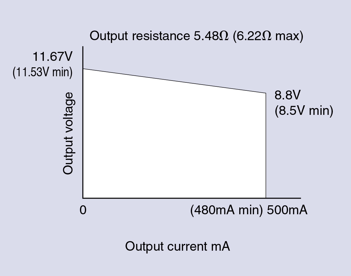
Having maximised the usable intrinsically safe power output from the interface in the safe area, this power has to be safely transmitted to the hazardous area apparatus located in Zone 0 or 1. To limit stored energy, international intrinsic safety standards define the maximum capacitance and inductance that may be safely connected to any intrinsically safe source. These figures depended upon the gas in which the hazardous area apparatus is located, group IIC gases represented by hydrogen is the most incendive and therefore has the smallest allowance. The maximum voltage Uo determines the maximum capacitance Co that may be safely connected, and the maximum current Io determines the maximum inductance Lo. Fig 1 shows the output characteristics and intrinsic safety output parameters for a practical power supply using these techniques.
| Safety parameters |
Gas group | ||
| IIC | IIB | IIA | |
| Uo | 12.4V | 12.4V | 12.4V |
| Io | 2.66A | 2.66A | 2.66A |
| Po | 5.2W | 5.2W | 5.2W |
| Co | 1.24µF | 7.9µF | 30.0µF |
| Lo | 5µH | 20µH | 40µH |
| Lo/Ro | 4.3µH/Ω | 17µH/Ω | 34µH/Ω |
| Usable output |
Minimum output current 480mA Minimum output voltage 8.5V Minimum usable power 4.08W |
||
Figure 1 - Power supply output characteristics and intrinsic safety parameters
If the internal capacitance and inductance of the hazardous area load is isolated from it's input terminals, resulting in zero equivalent input safety parameters Ci and Li, all the allowable capacitance and inductance is available for the cable connecting the power supply to the hazardous area apparatus.
The maximum output voltage Uo of 12.4V allows a relatively large capacitance to be connected which does not impose any practical cable restrictions. However, in intrinsic safety terms, the large output current Io only allows a small inductance to be connected which restricts cable length, particularly in a group IIC hydrogen gas. Most twisted pair instrument cables have an inductance of less than 0.8µH/m, the maximum cable length between the power supply's output and the hazardous area apparatus will be:
| Gas group | |||
| IIC | IIB | IIA | |
| Cable length | 6m | 25m | 50m |
Table 1 - Maximum cable length defined by power supplies Lo
As an alternative to using the allowable inductance Lo to define the maximum cable length, it is acceptable to use a cable with an L/R ratio equal to, or less than the Lo/Ro of the power supply. Any length of cable may then be used, the maximum length being determined by the acceptable resistive voltage drop of the cable. This extends the maximum usable cable length for applications in IIB and IIA gases, but instrumentation cables having an L/R ratio of 4.3µH/Ω or less are not generally available, therefore it does not increase the permitted cable length in IIC gas applications for this power supply.
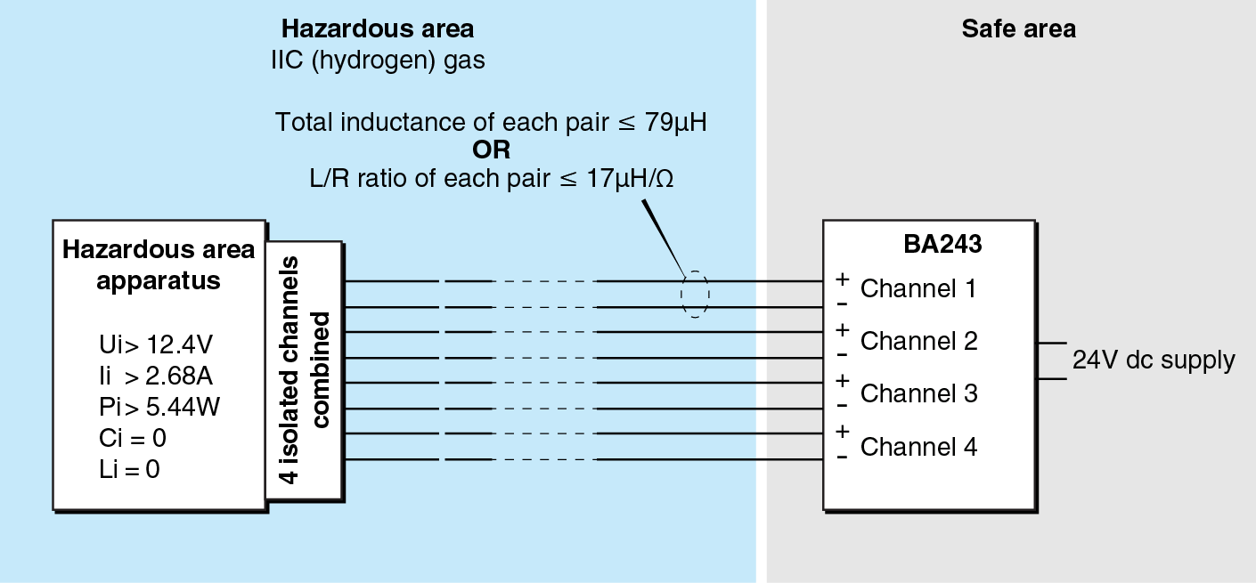
There are a number of ways of overcoming the restricted cable length for powering hazardous apparatus in group IIC hydrogen gases, but they involve other types of explosion protection such as Ex m encapsulation, Ex d flameproof or Ex e increased safety. A more elegant solution which retains the advantages of intrinsic safety, uses two or more galvanically isolated power supplies combined at the hazardous area apparatus thus reducing the current flowing in each conductor. Fig 2 shows a power supply with four identical, individually isolated intrinsically safe outputs, each channel having the output safety parameters shown in Table 2. If more than two channels are remotely combined, a redundant combining circuit is required which introduces an additional voltage drop of 1.1V. If a multicore cable is used, it must be a Type A or B cable.
Fig 2 Power supply with four isolated channels combined at the hazardous area apparatus
| Safety parameters for each channel |
Gas group | ||
| IIC | IIB | IIA | |
| Uo | 12.4V | 12.4V | 12.4V |
| Io | 0.67A | 0.67A | 0.67A |
| Po | 1.36W | 1.36W | 1.36W |
| Co | 1.24µF | 7.9µF | 30.0µF |
| Lo | 79µH | 317µH | 634µH |
| Lo/Ro | 17µH/Ω | 68µH/Ω | 137µH/Ω |
| Usable total output |
Minimum total output current 488mA Minimum output voltage (8.6V - 1.1V) = 7.5V Minimum total usable power 3.6W |
||
Table 2 Intrinsic safety output parameters of each channel and the combined total usable output of four channels.
By combining the output of the four identical interface channels at the hazardous area apparatus and using standard twisted pair cables with an inductance of 0.8μH/m, the maximum distance between the power supply and the hazardous area apparatus can be increased to:
| Gas group | |||
| IIC | IIB | IIA | |
| Cable length | 98m | 396m | 793m |
Table 3 Maximum cable length defined by Lo of each channel
Alternatively, any length of cable with an L/R ratio equal to, or less than, the Lo/Ro of each channel of the power supply may be used. Instrumentation cables having an L/R ratio of 17µH/Ω or less are available from multiple manufacturers, this allows long cables, only limited by their resistive voltage drop, to be used for IIC hydrogen applications.
The interface between the safe and hazardous areas, be it a Zener barrier, galvanic isolator or power supply with an intrinsically safe output, limits the voltage and current that can pass from the safe into the hazardous area. To prevent this energy being stored and suddenly discharged within intrinsically safe apparatus, all energy storing components are clamped to limit the stored energy to below the ignition threshold. Increasing the usable hazardous area power does not make this significantly more difficult, but the increased usable power is more likely to produce hot surfaces which can thermally ignite a flammable atmosphere. Hazardous area apparatus powered by an isolator with a usable output power of 4W requires careful power management design to ensure that the temperature of surfaces in contact with the flammable atmosphere can not cause ignition at the maximum operating temperature. This is achievable, although some components may require encapsulation to increase their surface area and thus reduce their surface temperature.
Whilst intrinsic safety remains by definition a low power protection concept, using the techniques summarised in this article extends the scope of intrinsically safe hazardous area apparatus to include apparatus consuming up to approximately 4W.
This article by BEKA Managing Director Olivier Lebreton CEng MIET was published in the November 2023 edition of Hazardex.
The techniques described in this article have been successfully used to design and certify the BA212 and BA243 Power Isolators for Pageant, an intrinsically safe Ex ia combined operator display panel and PLC with plug-in input and output modules for installation in Zones 1 or 21.